The foundation of stability: the bed as the basis of precision
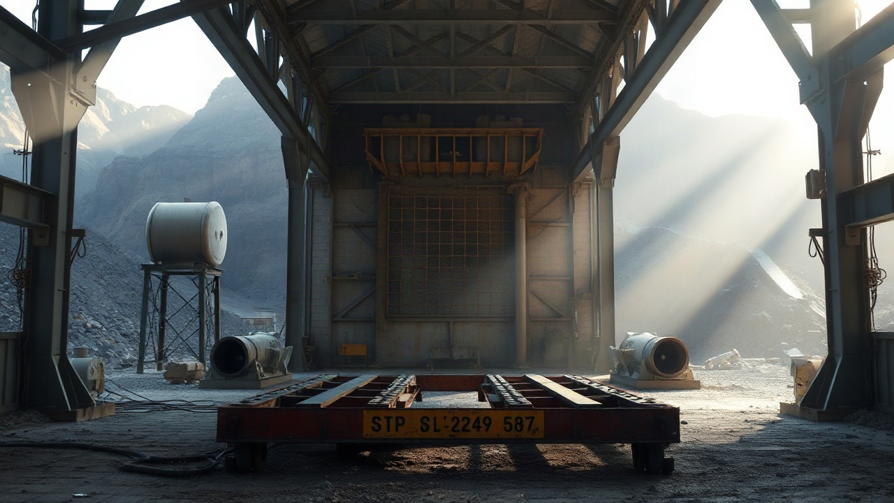
Any discussion of the precision of metalworking equipment begins not with the electronics, nor even with the cutting tool, but with the base on which all the assemblies rest. The bed is the foundation that determines the rigidity and vibration resistance of the whole system. In modern machine-tool building, the shift away from light welded structures in favour of massive castings has become the standard for precision equipment. The mass of the bed directly affects the machine’s ability to absorb the resonances that arise when the spindle runs at high speeds or during heavy milling with large stock allowances.
The traditional material remains high-quality grey cast iron, for example grade GG20 or GG30. However, modern precision requirements have led to the growing popularity of mineral casting (synthetic granite). This material is a mixture of granite grit of various fractions and epoxy resin. The key characteristic of mineral casting is its damping coefficient, which is almost ten times higher than that of cast iron. This means that any vibrations decay in such a base almost instantly, without reaching the cutting zone.
The geometry of the bed is designed using the finite element method. Engineers calculate the load distribution so as to minimise deformations under the weight of heavy workpieces and moving assemblies. Particular attention is paid to the symmetry of the structure. A symmetrical bed behaves more predictably under thermal expansion, keeping the relative position of the axes unchanged even when the workshop temperature fluctuates.
Comparison of bed materials
| Characteristic | Grey cast iron | Mineral casting | Welded steel |
| Damping capacity | Medium | Very high | Low |
| Thermal inertia | Medium | High | Low |
| Bending rigidity | High | Medium | High |
| Complexity of manufacture | High (casting + ageing) | Medium (mould casting) | Low (welding) |
An important stage in preparing the bed is the relief of internal stresses. For cast iron this may be several months of natural ageing in the open air or accelerated thermal ageing in furnaces. Without this procedure the bed may change its geometry by several microns during the first year of operation, which is unacceptable for a high-precision machine. Modern technologies also include vibration ageing, which makes it possible to stabilise the structure of the metal in a matter of hours.
The accuracy of the seating surfaces for the guideways on the bed is achieved by high-precision grinding or hand scraping. Scraping remains the gold standard for achieving a perfect mating of surfaces. Despite the advance of automation, a skilled craftsman can create a microrelief on the surface that retains an oil film and provides an accuracy of fit unavailable even to the most modern grinding machines. It is precisely these microscopic oil pockets that prevent the stick-slip effect during slow movements.
The bed also acts as a heat sink. In modern machining centres, channels for the circulation of a temperature-stabilising fluid may be provided inside the bed. This makes it possible to maintain a constant temperature across the whole structure, eliminating distortions caused by one-sided heating, for example from the sun through a window or from adjacent operating equipment. The rigidity and thermal stability of the bed are the invisible factor that distinguishes a prototyping machine from an industrial centre capable of holding a tolerance of three microns for years.
The spindle unit: the heart of the machining process
The spindle is the most heavily loaded and complex assembly of a CNC machine. Its characteristics determine not only the rate of metal removal but also the quality of the surface obtained. Modern spindles are high-technology devices that combine enormous power with precision accuracy of rotation. The main parameters here are the runout at the end of the arbor, which in top models does not exceed 1–2 microns, and the dynamic balancing that allows operation at speeds of up to 20 000 – 40 000 rpm without destructive vibrations.
Hybrid bearings with ceramic balls are used in the construction of spindles. Ceramic is lighter than steel, has a lower coefficient of thermal expansion and is not prone to welding to the races at high speeds. This makes it possible to substantially reduce the heating of the unit and increase its service life. The use of high-precision duplex or quadruplex bearing sets provides the radial and axial rigidity required for heavy milling of hard alloys.
The tool-clamping system has also evolved. The traditional BT and SK tapers are gradually being displaced by the HSK (Hollow Shank Cone) standard. During rotation, the hollow HSK cone is pressed even more tightly against the walls of the seat by centrifugal forces, providing a dual contact: on the taper and on the face. This guarantees exceptional repeatability of tool changes and rigidity of the system under high radial loads.
- Types of spindle cooling: air, liquid (cooling jacket), oil mist.
- Drive options: belt, direct (Direct Drive), integrated motor spindle.
- Monitoring sensors: vibration, bearing temperature, shaft displacement.
Motor spindles (integrated drives) represent the pinnacle of the evolution. The absence of intermediate links such as belts or couplings eliminates backlash and unnecessary vibrations. However, such a design requires a complex control system and intensive liquid cooling, since the heat from the motor windings is released directly inside the unit. To compensate for thermal expansion, modern CNC systems use mathematical models that correct the tool projection on the fly depending on the spindle temperature.
The balancing of the assembled spindle unit is carried out on special stands. Even a slight imbalance at high speeds turns into a powerful centrifugal force that not only spoils the surface cleanliness of the workpiece but also cuts the service life of the bearings in an avalanche. That is why manufacturers pay attention not only to the spindle itself but also to the quality of the chucks and arbors used, which must have a balancing grade of no lower than G2.5.
Special attention in modern machines is paid to protecting the spindle from collisions. Load-monitoring systems are able, in fractions of a millisecond, to detect a sharp spike in current or vibration that occurs on contact with an obstacle and to stop the feed before irreversible damage occurs. This is critically important given the cost of a high-speed spindle unit, which can amount to as much as a third of the cost of the whole machine.
The mechanics of movement: ball screws and guideways
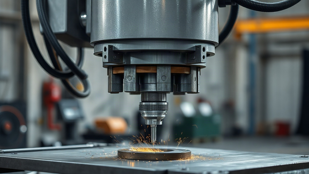
To realise the movements calculated by the CNC system, linear guideways and ball screws (ball screw assemblies) are used. The task of this pairing is to convert the rotary motion of the servomotor into the linear motion of the table or column with maximum accuracy and minimum friction. Modern machines use rolling guideways (profile rails) or sliding guideways. Profile rails with rolling elements provide high dynamics and travel speeds of up to 60–100 metres per minute while maintaining high rigidity.
Ball screws are a critical element of the positioning chain. Precision machines use pairs of accuracy class C3, C1 or even C0. The number after the letter C indicates the maximum permissible deviation of the screw pitch over a given length. To eliminate axial backlash in the ball screw, preload is applied — the use of two nuts or of a single nut with balls selected to a slightly larger diameter. This guarantees that there will be no “dead travel” on reversal (a change of direction).
Accuracy classes of ball screws to the ISO standard
| Accuracy class | Tolerance over 300 mm of length (µm) | Field of application |
| C0 | 3 | Reference measuring machines |
| C1 | 5 | Precision grinding machines |
| C3 | 8 | High-precision machining centres |
| C5 | 18 | Standard milling machines |
One of the main problems with ball screws is heating during intensive operation. Friction in the screw-nut pair and in the support bearings leads to elongation of the screw. With a screw one metre long, a temperature rise of just one degree causes an elongation of 11–12 microns, which instantly takes the machine outside its tight tolerances. To combat this, hollow screws with forced oil cooling are used, or the screw is pre-tensioned during assembly to compensate for future expansion.
In recent years, in high-dynamic machines, ball screws have been giving way to linear motors. In such a system there are no rubbing mechanical pairs transmitting the motion — the moving part literally levitates in a magnetic field above the stator. This makes it possible to achieve incredible accelerations (up to 2g and higher) and eliminates the wear of mechanical components. However, linear motors release a great deal of heat and require powerful magnetic shields to protect against metal chips.
Sliding guideways coated with special anti-friction materials of the Turcite-B type are still indispensable in heavy machines. They have better damping properties compared with rolling guideways. This makes it possible to carry out heavy-duty machining of difficult-to-cut materials such as titanium or Inconel with large depths of cut, where vibrations on rolling elements could lead to tool breakage.
The lubrication of all the moving units is automated. A centralised system delivers a strictly metered quantity of oil or grease to each carriage and ball-screw nut at set time intervals or after a set distance travelled. A lack of lubrication leads to microscoring, which instantly affects positioning accuracy and smoothness of travel. Modern CNC systems monitor the pressure in the lubrication system and block operation of the machine at the slightest deviation from the norm.
Intelligent control: the capabilities of the CNC system
The numerical control system is the brain of the machine, interpreting G-code and controlling the drives in real time. A modern CNC unit is a powerful computer with a real-time operating system, capable of processing thousands of blocks of the control program per second. One of the most important functions is Look-Ahead . The system analyses the trajectory hundreds of steps ahead, reducing speed in advance on sharp turns and corners so that the inertia of the massive assemblies does not cause a deviation from the set contour.
Interpolation is another cornerstone of control. The machine does not simply move point to point; it builds smooth curves (NURBS interpolation), which is critically important for surface quality when making moulds and dies. Without smooth interpolation, the surface of the part would consist of microscopic steps, visible to the eye and requiring hand polishing. Modern controllers ensure the smoothness of the trajectory at the nanoscale.
Jerk-control functions make it possible to manage acceleration. A sudden change in acceleration causes vibrations in the machine’s mechanics. By smoothly ramping the motor current up and down, the CNC system protects the mechanics and makes it possible to achieve higher accuracy at high feed rates. This is reminiscent of the work of a professional driver, who presses the pedals smoothly, keeping the car stable through a bend.
- The main tasks of the CNC system: geometric error compensation, dynamics control, tool-change management, monitoring of sensor states.
- Popular architectures: closed (Fanuc, Heidenhain) and open (based on an industrial PC).
- Communication interfaces: Ethernet, EtherCAT, Profinet for integration into a single enterprise network.
Modern CNC systems support adaptive control. The machine measures the load on the spindle in real time and, if the material turns out to be harder or the stock allowance greater than calculated, automatically reduces the feed. This prevents tool breakage and scrapped parts. There is also a wear-compensation function: after measuring the tool with a special sensor, the system makes corrections to the trajectory, taking into account the loss of a few microns on the cutting edge.
Diagnostics and service have also reached a new level. The CNC unit collects statistics on the operation of each assembly, predicting the possible failure of bearings or guideways. Many manufacturers offer remote access to the machine over secure communication channels, which allows engineers to carry out diagnostics and parameter adjustment without travelling to the site, substantially reducing equipment downtime.
Visualisation of the process on the unit’s screen has become practically indistinguishable from reality. The operator can run a 3D simulation of the machining directly before pressing the “Start” button. The system will check the program for gouges, collisions with the tooling or excursions beyond the working travel. This is especially important in multi-axis machining, where the tool trajectories can be extremely complex and counterintuitive for a human.
Multi-axis machining: geometry without limits
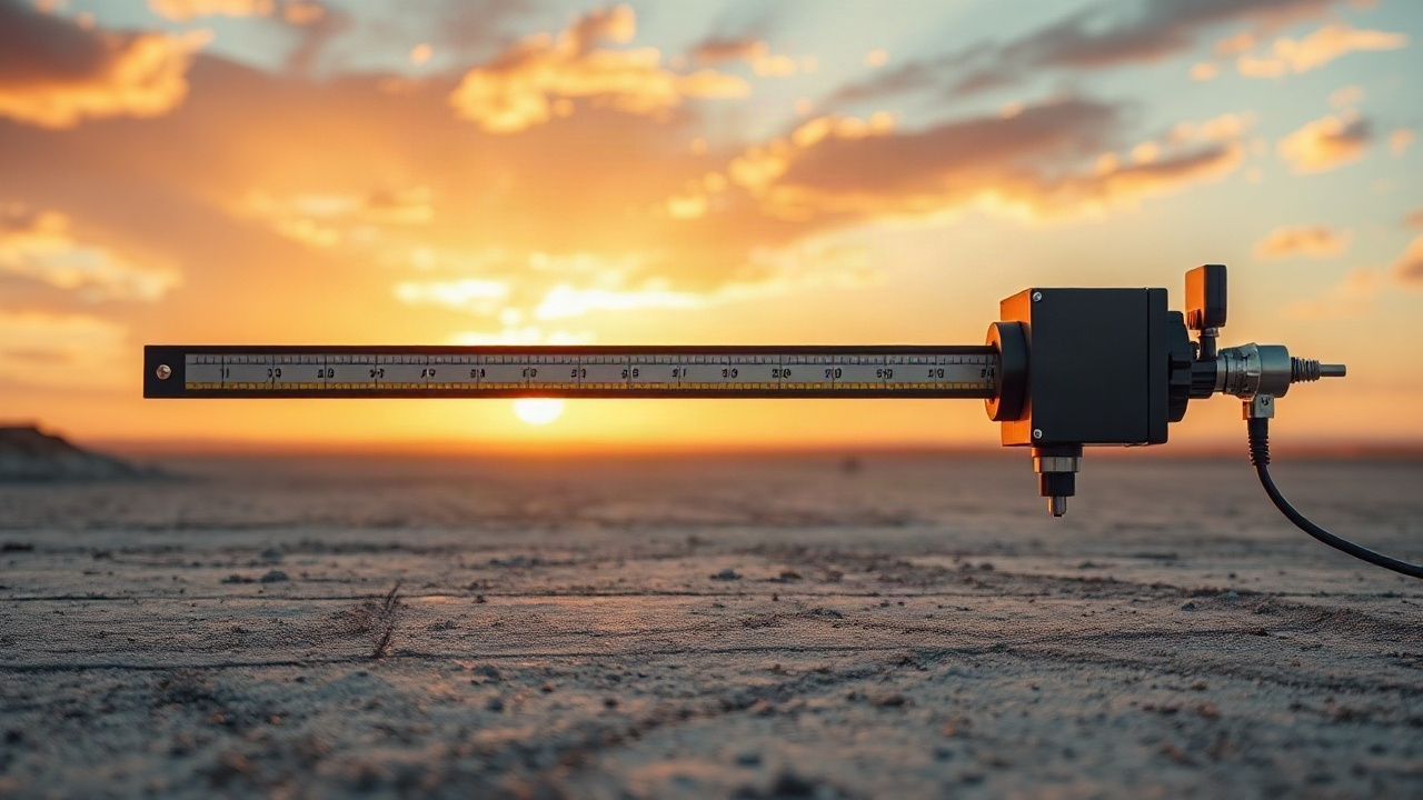
The transition from the classic three axes (X, Y, Z) to five-axis machining brought about a revolution in precision and efficiency. A five-axis machine has two additional rotary axes (usually A and B, or B and C), which allows the tool to approach the part at any angle. The main advantage here is not even the complexity of the shapes, but the ability to machine a part from five sides in a single set-up. Every re-clamping of the part in a vice is an inevitable loss of locating accuracy. Five-axis machining reduces these losses to zero.
There are two modes of operation: positional machining (3+2) and continuous five-axis machining. In the first case, the rotary axes position the part in the required orientation and are rigidly locked with brakes, after which ordinary three-axis milling takes place. This provides maximum rigidity. In the continuous machining mode, all five axes move simultaneously, which makes it possible to create the most complex surfaces, such as turbine blades, impellers or elements of aerospace structures.
To control five axes, the TCPM (Tool Center Point Management) function is required. It automatically compensates for the displacement of the tool tip when the spindle or table is tilted. Without this function, programming five-axis machining by hand would be impossible, since a one-degree rotation of an axis can shift the tool tip by tens of millimetres. The CNC recalculates these displacements thousands of times per second, keeping the cutter exactly on the set trajectory.
Comparison of 5-axis machine configurations
| Type of construction | Advantages | Limitations |
| Tilting rotary table (Trunnion) | High rigidity, large tilt angles | Limitation on workpiece weight |
| Swivel head + table | Ability to machine long shafts | More complex kinematics calibration |
| Double swivel head (Gantry) | Machining of very large parts | Lower rigidity compared with a table |
The accuracy of a five-axis machine depends largely on the accuracy of determining the centres of rotation of the rotary axes. For this, special calibration procedures are used with a high-precision reference sphere and a measuring probe. The machine automatically measures the sphere in different positions of the rotary axes and makes corrections to its kinematic model. This procedure makes it possible to compensate for microscopic errors of assembly and mechanical wear.
The use of five axes makes it possible to use a shorter and more rigid tool. On a three-axis machine, machining deep cavities would require a long cutter, which is prone to deflection and vibration. On a five-axis machine you can tilt the spindle or the part, approaching the required zone with a short tool at the optimal angle. This not only increases accuracy but also radically improves surface cleanliness, since the cutter works with its side, not its centre, where the cutting speed is close to zero.
Programming five-axis machines requires advanced CAM systems. The trajectory-calculation algorithms must take into account not only the geometry of the part but also the dimensions of the machine itself, in order to rule out collisions of the spindle with the table or tooling. Modern machining strategies make it possible to maintain a constant load on the tool, which extends its life and ensures dimensional stability across the whole batch of parts.
Thermal stability: control of expansion
Temperature is the chief enemy of precision. All materials expand when heated, and for a machine working to tolerances of a few microns this becomes a serious challenge. The sources of heat are not only the cutting processes but also the motors, bearings, hydraulic systems and even the lighting in the workshop. Uneven heating leads to warping of the bed and drifting of the axes. High-precision machines employ a set of measures to ensure thermal stability.
The first line of defence is active cooling. Liquid temperature-stabilisation systems pump coolant through the most heavily loaded assemblies: the spindle, the axis motors and the ball-screw nuts. The coolant temperature is maintained to within tenths of a degree relative to the temperature of the bed. In this way, the heat is removed into the cooler (chiller) before it can be transferred to the machine’s structure.
The second aspect is structural symmetry. If a machine is designed so that the heat sources are located symmetrically relative to the working axes, then expansion will occur evenly, without causing distortions. Portal (gantry) structures, for example, are far more stable than cantilever ones for precisely this reason. Engineers also strive to isolate the bed from the coolant tank and the hydraulic station, moving them outside the machine’s main body.
- Methods of combating thermal deformations: thermosymmetric design, forced cooling, software compensation, the use of materials with a low CTE.
- CTE (coefficient of linear thermal expansion): a key parameter when choosing materials.
- Infrared sensors: monitoring the temperature of the workpiece and the tool.
Software compensation of thermal expansion is an intelligent way of increasing accuracy. Temperature sensors placed at critical points on the machine transmit data to the CNC. On the basis of a pre-created mathematical model, the system calculates how much the spindle has lengthened or the column has shifted and automatically applies a correction to the coordinates. This makes it possible to start work immediately, without waiting hours for the machine to “warm up” to its working state.
Particular attention is paid to the temperature of the cutting fluid (coolant). The enormous volumes of fluid washing over the part during cutting can act both as a cooler and as a heater. In precision production, coolant tanks are fitted with powerful refrigeration units so that the fluid temperature matches the ambient temperature. This eliminates thermal shock to the workpiece at the start of machining.
Even the air in the workshop plays a role. In precision-mechanics laboratories a constant temperature of 20 degrees Celsius is maintained with minimal deviations. For machines working in ordinary workshops, manufacturers create fully enclosed cabinets with their own climate-control system. This makes it possible to isolate the machining zone from draughts and sharp temperature swings when the workshop doors are opened in winter.
Measuring systems: the eyes and ears of the machine
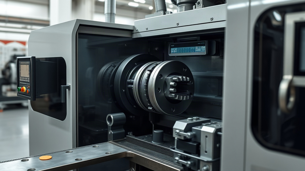
Without quality feedback, any mechanics is powerless. A modern CNC machine is equipped with a whole arsenal of measuring systems that allow it to “see” its real position and the state of the tool. On the axes of travel are installed optical scales (glass scales) with a resolution down to nanometres. Unlike encoders on the motors, the scales measure the movement of the working element (the table) directly, eliminating the errors introduced by backlash and thermal expansion of the ball screw.
To check the geometry of the part right on the machine, wireless measuring probes are used. They make it possible to find the datum of the workpiece automatically, to measure centre distances or the diameters of holes after machining. This eliminates the human factor during set-up and makes it possible to implement the concept of “active control”, where the machine itself decides on the need for an additional finishing pass on the basis of the measurements obtained.
Tool measurement is another critical area. Laser measuring systems (Laser Tool Setters) are able to check the diameter and length of the cutter at working spindle speeds. This makes it possible to account for the dynamic runout and thermal projection of the tool. In addition, the laser instantly detects the breakage of a micro-tool 0.1 mm in diameter or less, which is impossible to do with a mechanical contact sensor without risking breaking the cutter itself.
Types of feedback sensors
| Type of sensor | Operating principle | Advantages |
| Rotary encoder | Optical disc on the motor shaft | Reliability, low cost |
| Optical scale | Scanning of a glass scale | Direct measurement, backlash compensation |
| Contact probe | Circuit closure on contact | High accuracy of part referencing |
| Laser sensor | Interruption of a laser beam | Non-contact tool measurement in motion |
Tool-condition monitoring systems analyse acoustic emission and the vibration spectrum. A blunted tool begins to vibrate at certain frequencies that the machine recognises before the surface quality deteriorates. This makes it possible to replace the insert in good time, preventing the scrapping of a costly workpiece. Some systems also measure the torque on the spindle, which helps to optimise cutting parameters on the fly.
Integrating the measuring systems into a single machining cycle makes it possible to implement adaptive technology. For example, when machining thin-walled aircraft parts that are prone to deformation after stress relief, the machine can take intermediate measurements and recalculate the trajectory for each subsequent pass. This guarantees compliance with the tolerance even under conditions of unstable semi-finished geometry.
It is important to note the role of collision-monitoring systems. In addition to software simulation, there are hardware sensors that track accelerations along all axes. In the event of the slightest impact, the system retracts the tool within milliseconds, saving the spindle and expensive tooling from catastrophic damage. Modern measuring systems turn the machine from an actuating mechanism into an intelligent measuring laboratory.
Tools and tooling: the last micron
However precise the machine, the final result always depends on the cutting tool and the way it is held. Modern CNC machining uses precision chucks: shrink-fit chucks (Shrink-fit) and hydraulic chucks. In shrink-fit chucks the tool is clamped by the thermal contraction of the holder, which provides practically ideal centring and minimal radial runout (less than 3 microns). This makes it possible to work at speeds above 30 000 rpm without loss of quality.
The cutting tool itself is made from fine-grained carbides with multilayer nanocoatings (TiAlN, AlTiN, DLC). The coatings act as a thermal barrier, allowing the heat to go into the chips rather than into the body of the tool or the part. The geometry of the edges is calculated so as to minimise cutting forces and rule out self-oscillation (chatter). Tools with a variable tooth pitch and a variable helix angle effectively dampen resonances, making it possible to remove more metal in a single pass.
The tool-change system in modern machining centres works at lightning speed. The “chip-to-chip” time can be less than two seconds. Tool magazines can hold hundreds of positions, which makes it possible to machine the most complex parts entirely in automatic mode. At the same time, each tool has its own electronic passport (an RFID tag on the holder) storing information about its projection, diameter and remaining service life.
- Types of holder: ER collet, shrink-fit, hydraulic, heavy-duty milling chucks.
- Tool materials: carbide, ceramic, cubic boron nitride (CBN), diamond (PCD).
- Methods of coolant delivery: through the spindle (internal delivery), oil mist, cryogenic cooling.
Internal coolant delivery under high pressure (up to 70–100 bar) is critically important when drilling deep holes and milling enclosed cavities. The fluid is delivered directly through channels inside the tool into the cutting zone, effectively flushing out chips and preventing them from being re-cut. This not only improves surface cleanliness but also multiplies the service life of costly cutters and drills.
The tooling for holding the part has also evolved. Zero-Point systems make it possible to set vices or fixtures on the machine table with a repeatability of within 2–5 microns in a matter of seconds. This is the basis of flexible automated production. While the machine machines one part, the operator sets up the next on a satellite (pallet), after which the pallets are changed automatically by a robot or a pallet changer.
In conclusion, it is worth noting the role of digital twins. The modern CNC machining process begins long before the workpiece reaches the table. A complete digital copy of the machine, tool and tooling makes it possible to fine-tune the technology down to the smallest detail in a virtual environment. The accuracy of the simulation is so high that the very first part to come off the machine meets every requirement of the drawing. This is the modern anatomy of precision — a symbiosis of perfect mechanics, smart electronics and digital technology.