Choosing the software and file formats
Working with a CNC machine begins long before the cutter ever touches the material. Everything rests on a clean vector. Unlike raster images, vector files describe geometry through mathematical formulas, which lets you scale them without any loss of quality. Layouts are most often created in Adobe Illustrator, CorelDRAW or dedicated CAD systems such as AutoCAD and Rhinoceros. The choice of software depends on the complexity of the product: for decorative cutting a graphics editor is enough, while computer-aided design systems are better suited to engineering parts.
The single most important aspect is the export format. Most machines understand files with the extension DXF, DWG, EPS or SVG. Each format, however, has its own quirks. DXF, for example, is the industry standard, but if it is exported incorrectly it can break smooth curves into hundreds of tiny straight segments, forcing the machine to move in jerks. SVG is excellent for laser cutting, yet it sometimes reproduces the real dimensions of an object incorrectly when imported into CAM software. It always pays to check the final file in verification software before sending it into production.
When working in graphics editors, it is important to keep units of measurement in mind. Professionals always work in millimetres. Scale errors are one of the most common causes of scrap, when instead of a 100 mm part the machine tries to cut an object 100 inches or pixels in size. Before you start drawing, make sure the work area is set up correctly and that the snap grid matches your production requirements.
Vector geometry and clean lines
An ideal CNC layout is not just a pretty picture but a precise toolpath. The first rule: all contours must be closed. If a line has a gap of even 0.01 mm, the CAM software cannot determine where the inside of the part ends and the outside begins. This leads to an error when generating the control program (the G-code). To check that a contour is closed, simply try to fill it with colour in the editor — if the fill “leaks out” or fails to apply, look for the gap.
The second critical requirement is the absence of overlaps and double lines. Beginners often copy objects on top of one another, creating duplicate contours. To the human eye this is invisible, but the machine will pass over the same place twice. This not only increases machining time but can also set the material on fire (in laser cutting) or break the cutter through excessive friction. Removing duplicates is a mandatory step in prepress preparation.
The number of nodes (points) on a curve should be optimal. Too many points make the toolpath “noisy”, forcing the machine controller to constantly calculate micro-accelerations and decelerations. Too few points will turn a smooth circle into a polygon. Use contour simplification tools (Simplify) to strike a balance between line smoothness and a lightweight file. Remember that a perfect vector is built on the smallest possible number of anchor points.
Accounting for tool diameter and fillet radii

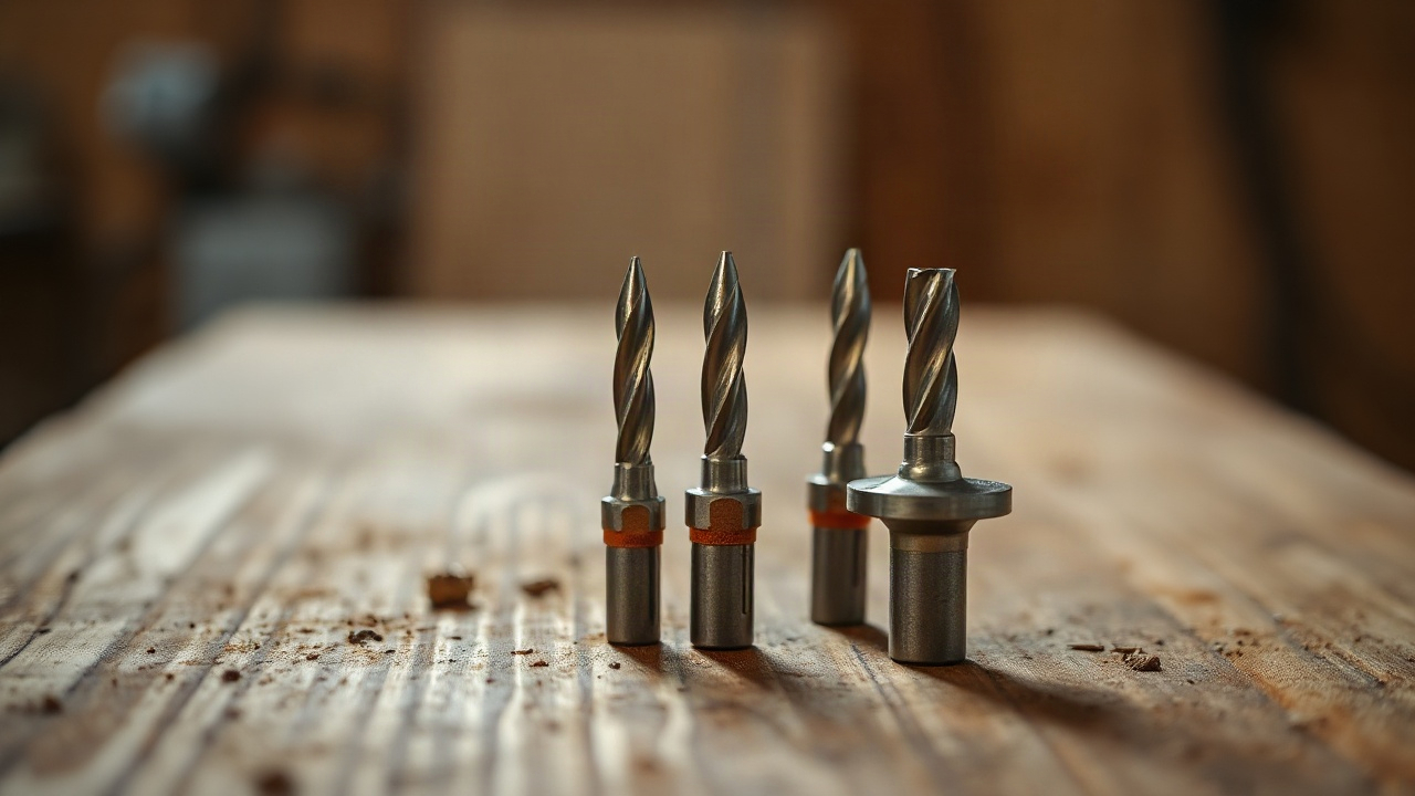
Unlike virtual space, where a line has no thickness, a physical cutter has a definite diameter. This imposes serious constraints on the design. You cannot cut a sharp 90-degree internal corner with a round cutter — there will always be a radius in the corner equal to half the tool diameter. If the part has to mate with another rectangular part (in a tongue-and-groove joint, for example), this becomes a problem.
To solve this, special techniques are used, such as “dog-bone” or “t-bone” fillets. These are small additional cut-outs in the corners that allow the mating part to seat fully. The designer must know in advance which cutter will do the job. Cutters of 2, 3, 4 or 6 mm in diameter are typically used. The smaller the diameter, the more finely the corners can be detailed, but the slower the process runs and the higher the risk of breaking the tool.
Comparison of common cutter diameters
| Cutter diameter (mm) | Minimum internal radius | Typical application | Tool strength |
|---|---|---|---|
| 1.0 – 2.0 | 0.5 – 1.0 mm | Fine detail, inlay work | Low (fragile) |
| 3.175 (1/8″) | 1.58 mm | Cutting plywood up to 6 mm, souvenirs | Medium |
| 6.0 | 3.0 mm | Furniture panels, rough cutting | High |
Kerf compensation and allowances
When preparing a layout, it is important to understand how the software will interpret a line. There are three types of processing: On center, Outside and Inside. If you draw a 100×100 mm square and the machine runs the centre of the cutter along that line, the final size of the piece will be smaller by the cutter diameter. Professional preparation means that the designer either builds in the offset themselves (Offset) or leaves it to the CNC operator, clearly marking the boundaries of the piece.
Allowances are also necessary for subsequent finishing. If a piece is going to be sanded, it will lose from 0.1 to 0.5 mm in size. In precise engineering parts this is critical. You should also take into account the tolerances of the material itself: plywood 10 mm thick may in fact be 9.5 mm or 10.5 mm. If your layout relies on grooves and joints, always design them around the real measurements of the material taken with callipers, rather than the nominal values from the catalogue.
Layer organisation and the sequence of operations
A well-built layout is always split into layers. This is not merely a matter of tidiness but a requirement of safety and process logic. The machine performs operations in sequence, and that sequence is critically important. Internal holes, engraving and pocketing are always done first, and only at the very end is the part cut out along its external contour. If you cut the part along the outer contour first, it may shift or vibrate under the cutter when you try to make the internal holes.
- Layer 1: Engraving. Lines or fills cut to a minimal depth.
- Layer 2: Pocketing (pockets). Areas where material is removed to a set depth without cutting all the way through.
- Layer 3: Internal holes. Through cut-outs inside the main part.
- Layer 4: External contour. The final cut, separating the part from the blank.
Colour-coding the layers helps the operator quickly set the parameters for each operation. Red, for example, means cutting, blue means engraving and green means marking. This approach minimises the risk of an error in which the machine accidentally cuts clean through the blank where only a light decorative line was intended.
Holding tabs and retaining the part
During milling, enormous cutting forces act on the part. If the part is small, once the final contour is finished it can be “shot out” or dragged under the cutter, ruining both the piece and an expensive tool. To prevent this, tabs (tabs/bridges) are placed in the layout or CAM software — small uncut sections of material that hold the part inside the blank sheet.
The size and number of tabs depend on the material and the size of the piece. For 6 mm plywood, tabs 3-5 mm wide and 2-3 mm high are usually enough. Once the work is finished, they are easily trimmed off with a chisel or knife and sanded flush. If you use a vacuum table, tabs may not be needed, but for mechanical clamping or screw fixing they are essential. Place them where they will be easiest to remove, avoiding complex radii and decorative elements.
Minimum spacing and material savings

When cutting several parts from a single sheet, there is a temptation to place them as tightly as possible. Yet there is a technological limit here. The distance between the contours of neighbouring parts must be greater than the diameter of the cutter used. It is best to leave a gap of 1.5–2 tool diameters. This is necessary to keep the leftover material (the skeleton) rigid — if the webs are too thin, they will start to vibrate and break, resulting in a poor cut or a broken cutter.
Effective nesting (arranging parts on the sheet) can save up to 30% of material. There are special automatic nesting algorithms that rotate parts to find the optimal position. But be careful: when working with wood it is important to take grain direction into account. If all the parts are turned at random to save space, the finished product may lose strength or look unattractive because of the mismatched wood grain.
Checklist before sending the layout into production
Before you save the final file, run through the list of typical mistakes. This will save time and money by sparing you the need to redo the work. Even experienced designers sometimes forget to convert text to curves or to delete stray junk points left over after editing. A thorough check is a mark of professionalism.
- All text objects have been converted to curves (Curves/Outlines).
- There are no intersecting or overlapping lines.
- All contours that require a through cut are closed.
- The layout dimensions match the real ones at 1:1 scale.
- Fillet radii in internal corners are set for the specific cutter.
- The layout is cleared of raster underlays, guides and hidden layers.
Preparing a layout is the bridge between an abstract idea and a physical object. The more precise and cleaner this drawing is, the more predictable the result will be. The machine is only an executor; it will reproduce exactly every mistake built into the vector. Put the quality of the geometry above visual beauty at the design stage, and your products will need minimal reworking once they come off the cutter.