The Specifics of Radius Milling for Creating Rounded Edges on Wooden Products
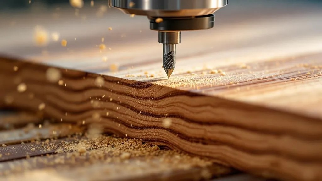
Radius milling, or edge rounding, is one of the most sought-after and critically important stages in producing high-quality wooden products. It is more than a decorative touch; it is a fundamental operation that directly affects the safety of use, the durability of the coating, the comfort in service and, of course, the aesthetic completeness of the final product. In the context of professional woodworking, the approach to this task must be exceptionally systematic and technologically precise. A poor or inaccurate rounding can ruin hours of prior work, from cutting to size to final sanding. For this reason, our company’s specialists pay particular attention to tool selection, machining parameters and quality control at this stage.
The main aim of radius milling is to eliminate sharp corners, which by their nature are points of stress concentration, are prone to rapid wear and pose a potential hazard to the user. From a technological standpoint, the process requires a deep understanding of the interaction between the cutting tool (the cutter) and the material (the wood) at the micro level, since the result depends on numerous variables, including the hardness and moisture content of the wood, as well as the feed rate and spindle speed. This machining method is used both in furniture manufacturing and in producing mouldings, architectural elements and specialised wooden structures. Precision and cleanness of machining are in this case not merely wishes but strict production standards.
🔍 The Basics of Radius Milling: Aims and Technological Essence
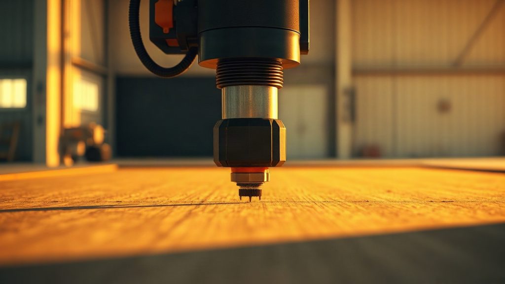
Radius milling is a machining method in which the sharp edge of a part is replaced by a smooth, arc-shaped surface with a defined radius R. Technologically, this is achieved using a profile cutter with a concave cutting section that precisely matches the required convex profile. Unlike a chamfer, which is a flat bevelled plane, radius rounding provides a continuous change in surface geometry, which is key to achieving the ergonomics and visual softness of the product.
The main production aim of this operation goes beyond simple aesthetic improvement. Sharp edges are the zones where coatings adhere worst, since as they dry a thin layer of coating forms on them, or premature abrasionoccurs. Rounding, even minimal, significantly increases the surface area in this critical zone, allowing the coating to form a sufficient thickness and ensure an even distribution of the protective layer, which extends the service life of the finish coat and, consequently, of the entire product. Without this stage, a high-quality finish on fronts, worktops or door leaves is unattainable.
The radius milling process involves several critical steps. It begins with surface preparation — the edge must be perfectly straight and perpendicular to the plane, which is usually achieved with a precise panel saw. Next comes the choice of cutter taking into account the required radius (from R1 to R10 and above) and the type of wood. Using an incorrectly sharpened or geometrically unsuitable tool will inevitably lead to defects such as chips, tear-out or waves on the surface being rounded, requiring labour-intensive manual rework. That is why our approach is always geared toward using precision tooling with carbide tips.
In the context of our production practice, radius milling also serves to improve product safety . In products intended for children, or in interior elements where frequent tactile contact is likely (railings, handles, worktops), a sharp corner is unacceptable. Even a small R2 or R3 rounding eliminates the injury hazard, making the surface pleasant to the touch and safe on contact. This is not merely a standards requirement, it is a principle of responsible manufacturing. In addition, furniture with rounded edges has a significantly reduced risk of damage during transport and installation, since sharp corners are the most vulnerable to impacts.
The technological essence of the operation lies in creating a perfectly smooth transition between two planes, which requires a steady feed and a high rotational speed of the spindle to minimise run-out and ensure an optimal cut. For hardwoods such as oak or ash, it is necessary to use multi-tooth cutters with a positive sharpening angle for a cleaner cut. For softwoods such as pine, a reduction in feed rate is sometimes required to prevent fibre tear-out. Moisture control of the blank is a mandatory condition, since machining excessively damp wood can lead to unevenness of the radius after subsequent shrinkage and deformation.
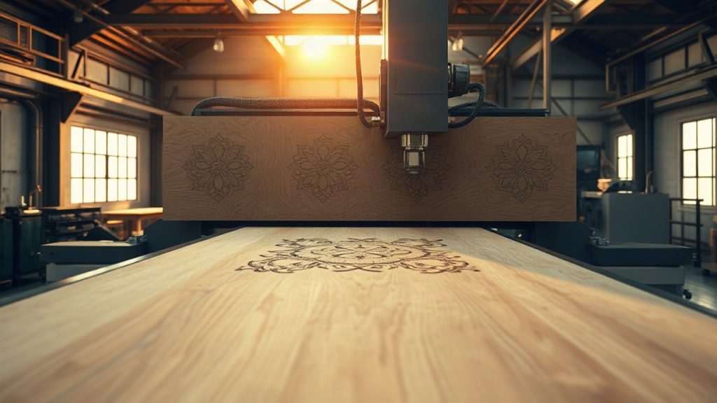
For large-batch production we use CNC milling machines, which ensure full repeatability of the profile and the highest precision along the entire length of the edge, eliminating the human factor. On such machines it is possible to perform not only simple rounding, but also complex combined profiles, where the radius part is combined with a chamfer or another decorative element. Setting up the machine is a multi-stage process involving precise positioning of the cutter in terms of height and projection, as well as calibration of the feed rate. Observing these parameters is critically important for the quality of the final cut.
In the end, radius milling is a comprehensive engineering taskthat requires not only the appropriate equipment but also the deep expertise of the operator. The quality of the rounding is the calling card of the product and directly indicates the level of the company’s production culture . We do not regard this stage as secondary, but as the final flourish in creating a flawless wooden product.
🛠️ Selection and Classification of Radius Cutters: Parameters That Affect the Result
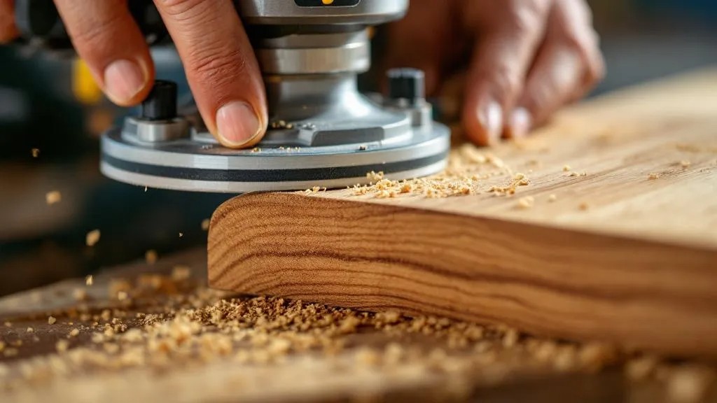
Choosing the right tool is a key factor determining the success and quality of radius milling. Radius cutters are a specialised type of cutter designed to create rounded profiles on edges. These cutters come in various designs, and each has its own areas of application and operating characteristics. The wrong choice of tool can lead not only to poor machining quality but also to premature failure of the cutter or machine itself, as well as to an increased risk of injury.
The main classification of radius cutters is based on the profile geometry and construction.
- Profile geometry: Cutters are divided into roundover bits (for creating a convex profile, a “positive” radius) and cove bits (for creating a concave profile, a “negative” radius). For rounding edges it is precisely roundover bitsthat are used. They are marked by radius, which determines the smoothness and size of the rounding.
- Construction: A distinction is made between solid cutters (usually for hand-held routers), assembled cutters (with replaceable knives) and cutters with a bearing. Cutters with a guide bearing are the most common in professional machining, since the bearing serves for precise referencing to the edge of the blank, ensuring a constant depth of milling, regardless of small variations in feed.
The material of the cutting part is a critically important parameter. For machining soft and non-abrasive wood species, high-speed steel (HSS)is generally sufficient. However, for hardwoods (oak, beech), wood-based panels (MDF, MFC), which contain abrasive binders, as well as for industrial volumes of production, cutters with carbide tips (HM/TC)are mandatory. Carbide provides a significantly greater tool life and allows high cleanness of the cut to be maintained over a long period, reducing the frequency of resharpening and equipment downtime.
The number of cutting edges (teeth) also affects machining quality and productivity. The more teeth there are, the lower the load on each edge and the cleaner the cut at the same feed rate. In high-speed industrial milling, the use of multi-tooth cutters is the standard. To reduce noise and improve chip removal, cutters with a spiral arrangement or an inclined angle of the cutting edges are used.
Balancing the cutter is not a technical whim but a safety requirement and a matter of precision. At rotational speeds reaching 18,000–24,000 revolutions per minute (rpm), even minimal imbalance causes vibration and run-out, which leads to a poor, wavy surface and excessive wear of the spindle bearings. That is why, for work on CNC machines and high-precision router tables, we use exclusively dynamically balanced tooling.
When choosing a cutter for a specific project, our specialists are guided by the following criteria:
- Required radius (R): Direct correspondence to the technical specification.
- Type of material being machined: Determines the choice of cutting-part material (HSS vs. HM).
- Production volume: Affects the choice between a solid and an assembled (with replaceable knives) design. Replaceable knives are economically advantageous for large volumes.
- Machine power: Large-diameter cutters and complex profiles require more powerful equipment.
Thus, choosing a cutter is a comprehensive engineering decisionthat must be based on a thorough analysis of all production factors. A correctly selected and prepared tool is the guarantor of high quality and the cost-effectiveness of the milling process.
⚙️ Cutting Parameters: Optimising Speed and Feed for a Clean Rounding
Correctly setting the cutting parameters is a cornerstone of radius milling technology. Cutting parameters mean the combination of spindle rotational speed and workpiece feed rate. These two parameters are inextricably linked and directly determine the surface quality, the load on the tool and the productivity of the whole process. Ignoring or incorrectly setting these parameters inevitably leads to thermal damage to the wood, fibre tear-out and premature dulling of the cutter.
The main indicator that must be controlled is the chip thickness or feed per tooth.
- Too high a feed per tooth (f_z > 0.5 mm): Leads to the formation of a thick chip, increased vibration, the creation of a large cutting force and, consequently, ragged edges and chips. The cutter begins to run out, and the surface quality drops sharply, requiring intensive subsequent sanding.
- Too low a feed per tooth (f_z < 0.1 mm): Leads to a scraping effect (instead of cutting), significant friction and overheating of the tool and the wood. The risk of burns (thermal damage) on the edge increases, especially on light species such as maple or birch. Also, a low feed reduces productivity without improving surface quality.
The spindle rotational speed should be as high as possible to achieve a clean cut. On industrial CNC machines the speed can reach 24,000 rpm. However, for large-diameter cutters (over 100 mm) or cutters with an unbalanced design, the speed must be reduced for safety reasons and to prevent excessive run-out. Tool manufacturers always specify the maximum permissible speed, which it is strictly forbidden to exceed.
The feed rate (v_f) is set by the operator and is the main tool for controlling f_z. For a finishing pass the feed rate should be lowerthan for roughing, in order to ensure a minimal chip thickness and the smoothest possible surface. When machining hardwoods the feed rate is also reduced compared with softwoods, to lessen the risk of fibre tear-out and ensure a stable cutting process. When working with end-grain edges (where the fibres run crosswise), a more cautious mode with reduced feed and speed is required, since end-grain wood is more prone to chipping.
Optimising cutting parameters is always a matter of finding a compromise between productivity and quality. In our practice, for each type of wood (for example, 40 mm solid oak, or an MDF panel) and each type of cutter, we use pre-calculated and empirically confirmed parameter tablesthat minimise the need for manual adjustment and guarantee a consistently high result. This technological discipline eliminates the occurrence of defects related to incorrect equipment settings.
🪵 The Influence of Wood Species and Texture on the Milling Process
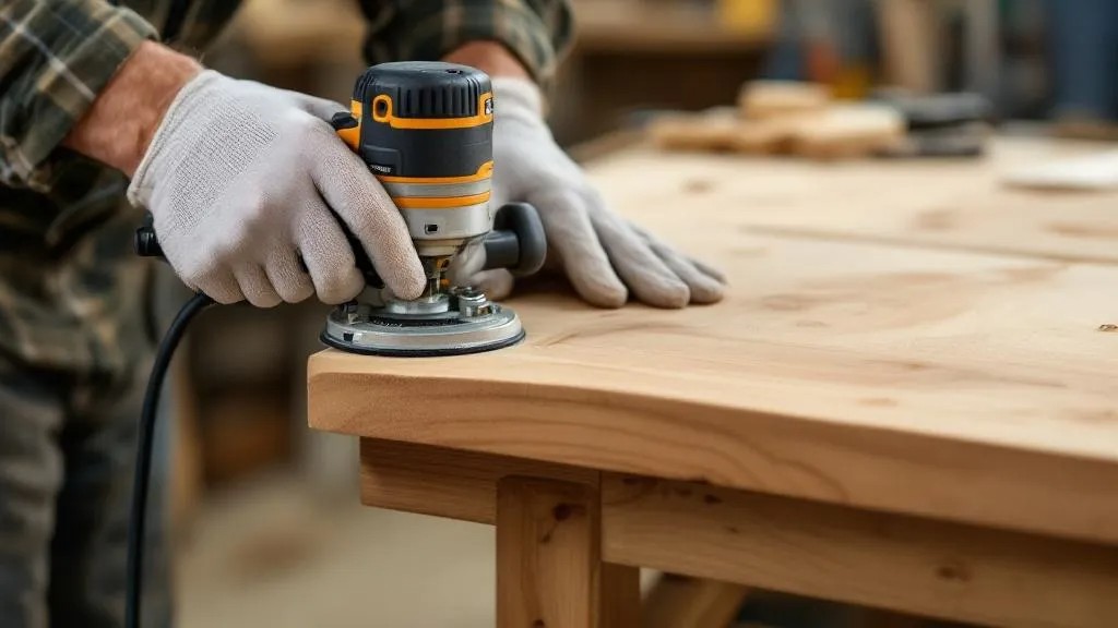
The characteristics of the wood being machined are a primary factorthat must be taken into account in radius milling. Wood is an anisotropic material, meaning that its properties, such as hardness, density, moisture content and grain direction, are not the same in different directions. This means there is no universal milling mode suitable for all species. Adapting the tool and the parameters to the specific material is a sign of high professionalism in woodworking.
The density and hardness of the wood directly affect the load on the cutter and the required power of the machine.
- Softwoods (pine, spruce, lime): They offer lower cutting resistance, which allows a higher feed rateto be used. However, soft wood is more prone to crushing and fibre tear-out, especially at the tool exit, which requires sharply honed blades and control of the exit of the cutter. Excessive rotational speed can lead to burns due to friction in the pores of the material.
- Hardwoods (oak, ash, beech, maple): They require a significantly greater cutting force and, accordingly, a reduced feed rate to maintain the optimal chip thickness f_z. For them, the use of carbide cutters (HM) and machines with high structural rigidity is mandatory to prevent vibration. Because of their dense structure, the risk of fibre tear-out is lower, but the risk of splitting increases with the wrong cutting direction.
The moisture content of the wood is one of the most treacherous parameters. Machining wood with elevated moisture (above 12%) leads to sticking of resin and fine chips to the cutting edges, which causes rapid dulling of the tool, increased friction and impaired cleanness of the surface. In addition, during subsequent drying the radius may deform or become uneven. Our company’s standard calls for milling only stabilised wood that has undergone kiln drying to a moisture content of 8–10% for furniture products.
The grain direction and texture determine the milling strategy. Milling should be done along the grain (climb milling) to achieve maximum cleanness. Milling against the grain (conventional milling) can lead to severe tear-out and the formation of a coarse, rough surface, especially in areas of interlocked grain or knots.
- The presence of interlocked grain (a chaotic interweaving of fibres, often around knots) requires special attention. In such places it is recommended to reduce the feed rate and use cutters with a high cutting cleanness (a greater number of teeth). Sometimes it is necessary to apply multi-stage machining or use manual milling with control of the direction.
- End-grain edges require a special approach. Since the tool crosses fibres arranged perpendicularly, the risk of chipping at the exit of the cutter is very high. To prevent this, we often use the method of “scalping” the edge (first a minimal radius is removed, then the full one) or use backing boards (sacrificial pieces) at the exit, which prevent fibre tear-out.
Thus, successful radius milling is the result of an intelligent approachthat takes into account all the internal characteristics of the material being machined, rather than simply performing the operation automatically. Only such an approach guarantees that even the most capricious material will be machined to a perfect smoothness.
📏 Precision and Control of Radius Geometry: Measuring Tools and Methods
Geometry control in radius milling is a mandatory element of the quality management system and is decisive for ensuring the product’s conformity with the design documentation and its functional compatibility with other elements. An inaccurate rounding not only spoils the appearance but can also create problems during assembly or when applying the finish coat.
The key task is maintaining the nominal radius R along the entire length of the edge. This requires both setup precision of the equipment and periodic inspection during production. At the first stage, the setup precision of the CNC machine or router table is achieved using digital indicators and calibration rulers. The cutter must be perfectly centred and set to the specified height relative to the surface of the blank, so that the cutting edge forms exactly half a circle.
For the direct inspection of the formed radius, specialised measuring instruments are used:
- Radius templates (radius gauges): This is a set of metal or plastic plates with convex and concave profiles of precise radii (for example, R1, R2, R3, etc.). The template is placed against the rounded edge, and the absence of a gap (a light gap) between the template profile and the edge surface confirms precise conformity with the nominal radius. This is the primary and fastest method of on-the-spot inspection.
- Profilometers and optical comparators: In high-precision production (for example, for exclusive furniture or architectural elements), more sophisticated optical and digital instruments are used. A profilometer makes it possible to obtain the exact profile of the edge and compare it with a reference CAD profile, detecting deviations in microns. An optical comparator projects a magnified image of the edge profile onto a screen with an applied grid or template.
The frequency of inspection is critically important. In serial production, inspection is carried out:
- Before starting a batch: Checking the first part after setting up the machine.
- Periodically during the process: Checking every Nth part (for example, every 10th or 20th), in order to track possible shifting of the tool due to vibration or wear of the bearing.
- After replacing or resharpening the tool: A mandatory check to confirm the restoration of the precision of the cutting edges.
Particular attention is paid to controlling the uniformity of the radius along the entire length of the part. On long edges (over 1 metre), deviationsmay occur, caused by deflection of the blank or inaccuracy of the machine’s guides. The operator must check the radius at both the startingand the end section of the milling. A non-uniform radius leads to problems during finishing (sanding) and installation, making the product unsuitable for applying varnish or oil.
The quality control process at our company includes mandatory recording of measurement results. If deviations exceeding the toleranceare detected, the process is stopped, the machine setting is adjusted or the tool is replaced . Thus, the precision of radius milling is ensured not only by modern equipment but also by strict metrological discipline.
⚠️ Preventing Defects: Chips, Burns and Fibre Tear-out
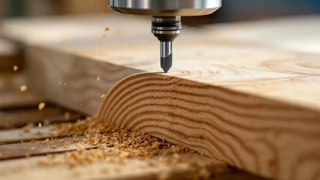
Radius milling, despite its apparent simplicity, is an operation that is quite prone to characteristic defects, which can significantly reduce product quality and increase the amount of subsequent manual rework. The main ones are chips, burns and fibre tear-out. Our production methodology is aimed at the comprehensive prevention of these problems through strict adherence to technological standards.
Chips are pieces of material breaking off the edge, most often occurring at the exit of the cutter or in areas of interlocked grain and knots.
- Causes: The use of a dull tool, too high a feed rate, the absence of sufficient support of the edge at the exit.
- Prevention measures: The use of sharply honed carbide cutters. The use of supporting elements (sacrificial or clamping strips) at the end of the blank to prevent fibre tear-out. Reducing the feed rate immediately before the tool exit. When working with end-grain edges, a two-sided pass is often used (milling first from one side to the middle, then from the other), or milling with a minimal allowance followed by manual rework.
Burns are thermal damage to the wood, manifested as brown or black marks on the rounded surface. This defect is especially noticeable on light species (maple, birch, pine) and cannot be removed without significant sanding.
- Causes: Excessive friction due to dulling of the cutter, too low a feed rate (the scraping effect), insufficient chip removal (re-cutting of chips) or working with elevated moisture of the wood.
- Prevention measures: Regular inspection and timely resharpening/replacement of the tool. Optimising the cutting parameters to ensure the optimal chip thickness f_z (not too small). Providing an effective extraction system for immediate removal of chips from the cutting zone, preventing them from re-entering it.
Fibre tear-out (or “pick-up”) is the tearing away of part of the fibres, which leads to a rough, uneven surface and is the most common defect when machining softwoods or during conventional milling.
- Causes: A cutting direction against the grain in areas of interlocked grain. The use of a cutter with a negative angle or a dull tool.
- Prevention measures: Strict observance of the milling direction along the grain. In problematic zones (interlocked grain), it is recommended to make two passes: first a roughing pass with minimal removal, then a finishing pass with the final radius. The use of cutters with a sharp positive sharpening angle and high rotational speed. On CNC machines it is possible to program a bypass of complex zones or a reduction in feed at critical points.
For the systematic prevention of defects, our work uses a process chart for each product, which clearly specifies:
- The type and geometry of the cutter.
- The optimal parameters n and v_f.
- The need to use supporting elements.
- The permissible tolerance for surface cleanness (for example, by R_z class).
A systematic approach to setup and control is the only reliable guarantee that finished products will have perfectly smooth and clean rounded edges meeting the highest standards.
💻 The Use of CNC Machines and the Automation of Radius Milling
The use of computer numerical control (CNC) machines has radically changed the approach to radius milling, especially in the context of serial and high-precision production. CNC machines provide unrivalled precision, repeatability and speed of machining, minimising the influence of the human factor and expanding the possibilities for creating complex profiles.
The key advantage of CNC lies in the stability of the cutting parameters. Unlike manual or semi-automatic milling, where the operator may feed the blank unevenly, a CNC machine guarantees a strictly constant feed rate v_f and a stable rotational speed of the spindle n. This is a fundamental condition for maintaining the optimal chip thickness f_z along the entire length of the edge, which in turn ensures a uniform cleanness and perfect geometry of the radius.
Programming the machining makes it possible to perform operations that would be extremely difficult or impossible in manual work. For example:
- Milling complex, variable radii: Creating an edge whose radius changes smoothly along the length of the part (for example, R5 transitions into R10).
- Combined profiles: Simultaneously creating a radius, a chamfer and a decorative groove in one pass using a multi-function cutter or several cutters in automatic tool-change mode.
- Working with internal corners: Milling a radius along the internal perimeter of a part, where high manoeuvrability and precision are required.
Introducing automatic tool change on CNC machining centres significantly increases productivity. When necessary, the machine can automatically replace a roughing cutter with a finishing one, or change an R3 cutter for an R5, without requiring the cycle to stop. This is critically important when manufacturing complex assemblies or large batches of diverse parts.
However, working with CNC requires high qualifications in the area of CAD/CAM systems. Creating the control program (CP) involves:
- Modelling the required profile in a CAD system.
- Selecting the toolpath for the tool’s movement (CAM system).
- Optimising the cutting parameters in accordance with the type of wood and tool.
- Post-processing (generating the G-code) and simulation to prevent collisions.
Effective management of chip removal is also automated. Modern CNC machines are equipped with powerful extraction systems integrated with the control program, ensuring maximum chip removal at the moment of cutting. This prevents clogging of the cutting zone, reduces the risk of burns and extends the service life of the tool.
Overall, the automation of radius milling on CNC machines allows our company not only to reduce the time of manufacturing, but also to achieve an extremely high and stable quality of surface, which is our competitive advantage in the market for high-quality wooden products.
🩹 Manual and Semi-automatic Milling Technologies: Features and Limitations
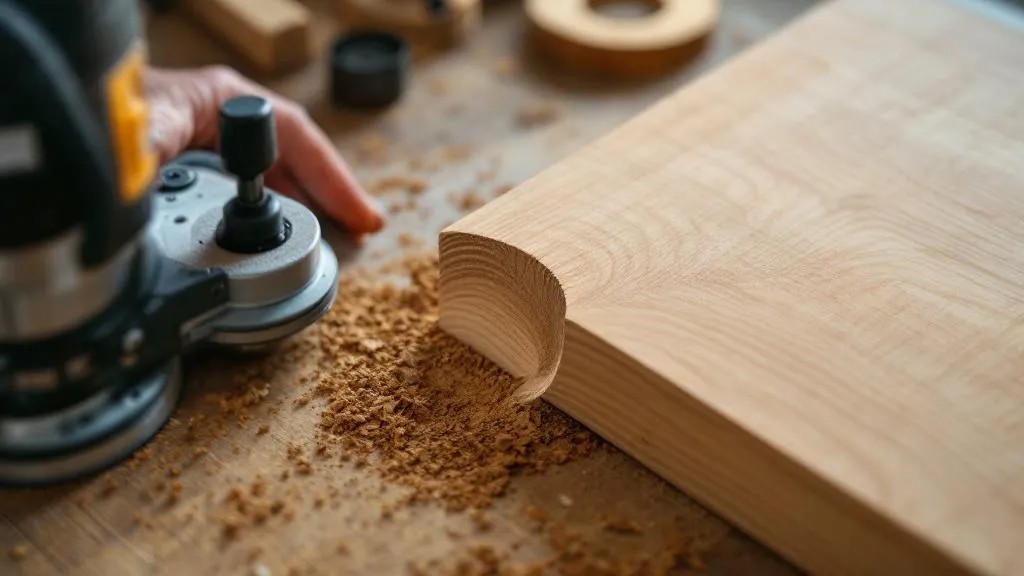
Despite the widespread use of CNC machines, manual and semi-automatic milling still holds an important place in the arsenal of woodworking production. These methods are indispensable when working with one-off, non-standard products, as well as in situations where it is economically impractical to program a complex machine. They require high qualificationsfrom the operator, but at the same time provide greater flexibility and the possibility of prompt intervention in the process.
Manual milling is carried out with a hand-held router (a trimmer or router), which is moved by the operator along the edge of the blank. The tool is fitted with a guide bearingthat slides along the unmachined surface, ensuring a constant depth of material removal.
- Advantages: Mobility, the ability to machine large-format parts that cannot be placed on stationary equipment (for example, built-in wall panels). Low initial costs for equipment.
- Limitations: Dependence on the human factor. The feed rate and the steadiness of holding the tool cannot be perfectly constant, which can lead to unevenness of the radius or waves on the surface. A higher risk of chips at the exit, requiring high accuracy from the operator. To obtain a quality result, several passes with a gradual increase in depth are required.
Semi-automatic milling is most often performed on a router table. This is stationary equipment where the milling head is fixed in place, and the blank is fed manually along guides or fences. This significantly increases stability compared with fully manual milling.
- Advantages: Better stability and precision compared with a hand-held machine. The ability to use more powerful and heavier cutters. Effective chip removal thanks to built-in extraction. The presence of adjustable clamping elements and guides makes it possible to control the position of the blank.
- Limitations: A limitation on the size of the parts being machined (depends on the size of the table). The need to use templates or fences for machining curved edges. The operator still controls the feed rate, which leaves a risk of defects arising from an unstable feed.
To achieve high quality in manual and semi-automatic milling, our company’s operators strictly observe the following rules:
- Using the sharpest possible cutters to minimise force and prevent tear-out.
- Smooth and even movement of the blank without jerks.
- Mandatory milling along the grain, even if this requires changing the direction of travel around the part.
- The use of “sacrificial” strips on the end grain to prevent chips at the tool exit.
In conclusion, manual and semi-automatic methods remain flexible and economically justified for small-batch and unique production. However, for mass production and guaranteed repeatability , CNC technologies are indispensable.
📐 Rounding versus Chamfer: Choosing the Profile and Its Functional Significance
The choice between radius rounding and a chamfer is one of the key decisions in developing the design and construction of a wooden product. Although both methods serve to eliminate a sharp corner, they have fundamental differences in aesthetics, functionality and application technology, and are not interchangeable.
A chamfer is a flat bevelled plane that connects two adjacent surfaces at an angle (usually 45 degrees). Its geometry is determined by two parameters: the width of the chamfer (the size of the bevelled plane) and the angle of inclination.
- Aesthetics: A chamfer gives the product a more austere, geometrically crisp and modern look. It emphasises the straightness and angularity of the design.
- Functionality: A chamfer effectively eliminates the sharpness, but leaves two new intersection lines (at the beginning and end of the chamfer), which can be points of stress concentration and weak spots for the paint coating. It is less ergonomic with frequent tactile contact.
- Technology: Easier to execute. It can be done with an ordinary straight cutter or even a hand plane.
Radius rounding is a smooth, arc-shaped transition, defined by a single parameter: the radius R.
- Aesthetics: Rounding gives the product softness, fluidity and a classic, more traditional look. It visually “softens” the geometry and makes the product more tactile.
- Functionality:The key advantage of rounding. Thanks to its smooth curvature, it:
- Optimises the application of the coating: The coating goes on in an even, thick layer, which many times over increases its durability.
- Improves ergonomics and safety: It fully eliminates sharp edges, making the edge comfortable and injury-safe (indispensable for children’s furniture and railings).
- Reduces vulnerability to damage: A rounded edge better withstands impacts and mechanical stress during transport.
- Technology: Requires a specialised profile cutter and more careful control of the cutting parameters.
The choice of profile must always be based on the purpose of the product and its styling.
- For kitchen worktops, school furniture or children’s toys radius rounding (R3 and above) is mandatory for reasons of safety and coating durability.
- For modern office desks or minimalist fronts a small chamfer or minimal rounding is often applied to preserve the austerity of the design while removing the sharpness.
In some cases, we apply combined profiles, where radius rounding is combined with a small chamfer to achieve a particular visual effect. The professional choice of profile is not merely following fashion, it is an engineering decisionthat must ensure the maximum service life and safety of the product.
🎨 Preparing Rounded Edges for Finishing and Coating
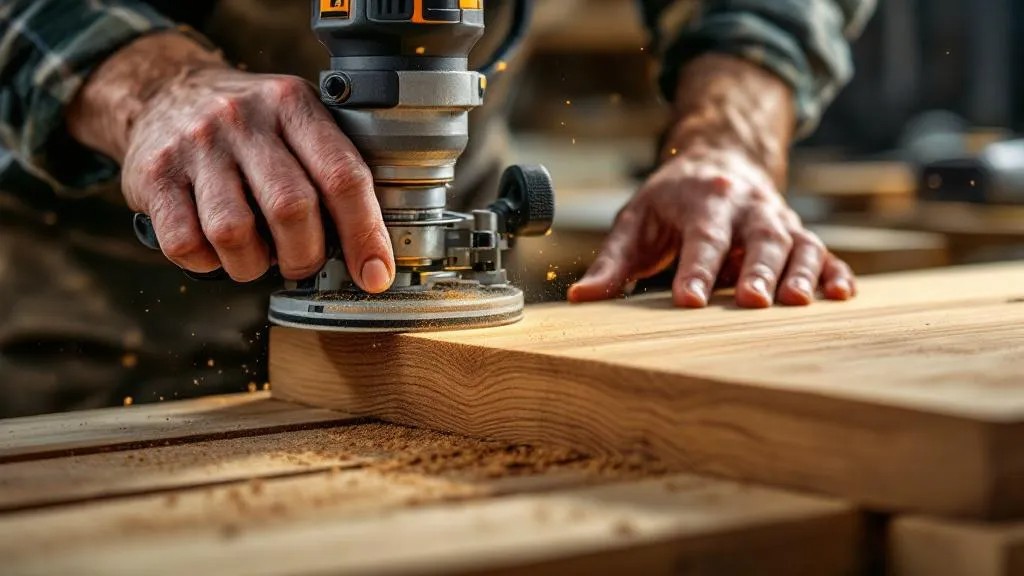
Perfectly executed radius milling is only the beginning of the process of preparing an edge for applying the finish coat (varnish, oil, paint). The quality of the subsequent sanding and cleaning of the rounded surface directly determines the appearance, uniformity and durability of the finish coat. Mistakes at this stage can nullify all the effort spent on precise milling.
Immediately after milling, the edge surface always retains microscopic marks from the cutting edges of the tool (so-called “waves” or “scratches”), as well as raised fibres of the wood. These defects become especially noticeable after applying the first coat of finish, which emphasises them. Therefore, a mandatory stage is multi-stage sanding.
The process of sanding a rounded edge requires special attention:
- Rough sanding (P100–P150): Carried out to remove the marks of the cutter and for the initial smoothing of the surface. At this stage it is important not to “round off” the radius, i.e. to preserve its geometry. For this, specialised sanding blocks are often used, with a shape exactly matching the radius R of the edge being machined.
- Intermediate sanding (P180–P220): Serves to remove deeper scratches from the rough machining and to prepare the surface for the finishing stages.
- Finish sanding (P240 and above): Used to achieve perfect smoothness and prevent the raising of fuzz after applying the primer.
The raising of fuzz is a phenomenon characteristic of wood, where fibres cut by the cutter stand “on end” on contact with water or the solvent contained in the coating. To minimise this effect, we often use the method of “water or alcohol raising”: before the final sanding the edge is slightly wetted (moistened), the fibres rise, and are then sanded off at the finishing stage. This ensures maximum smoothness after applying the finish coat.
A key aspect is preserving the geometry of the radius. In manual sanding, excessive pressure or the use of the wrong tool can lead to a flattening of the rounding, turning it into something between a radius and a chamfer. To prevent this, in large-batch production we use specialised edge-sanding machines or CNC centrescapable of machining the profile with a sanding belt or brush with precise control of the path.
Cleaning the surface before applying the coating is the final and no less important stage. Even the finest particles of sanding dust can spoil the quality of the coating, creating roughness or inclusions. To clean rounded edges, the following are used:
- Powerful blowing with compressed air (necessarily dry).
- Treatment with tack cloths or antistatic cloths to collect micro-dust.
Thus, radius milling sets the foundation for quality, but only careful and technologically precise preparation of the rounded edge for finishing guarantees that the finished product will have a flawless appearance and the maximum durability of the coating.
🔄 Tool Maintenance: Sharpening, Balancing and Care of Cutters
The durability, consistency of quality and safety of radius milling depend directly on the condition of the cutting tool. Tool maintenance is not an additional service but a mandatory and integrated stage of the production cycle, which includes regular sharpening, balance control and proper storage of the cutters.
Timely sharpening is critically important. A dull cutter does not cut but crushes and tears out the wood fibres, which leads to:
- Impaired surface cleanness: The appearance of tear-out and waves.
- Increased load on the machine: Higher power consumption.
- Overheating of the tool and the wood: The risk of burns.
- Reduced tool life: Excessive wear of the cutting edges.
We strictly monitor the working life of the cutters and send them for sharpening at the first signs of a decline in the quality of the cut. Sharpening of carbide (HM) radius cutters must be done on specialised sharpening machines with CNC and diamond wheels. The key task in sharpening is preserving the original geometry of the radius profile. Incorrect sharpening (a change in angle or radius) makes the cutter unsuitable for working with the specified profile.
Balancing the cutters is a mandatory procedure for tools working at high speeds (above 10,000 rpm), typical of radius milling.
- Static balancing: Used for relatively small cutters and eliminates the offset of the centre of gravity in one plane.
- Dynamic balancing: Used for large and assembled cutters. It eliminates imbalance in two planes, preventing vibration and run-out during rotation.
An unbalanced cutter not only spoils the quality of the surface by creating waviness, but also causes increased wear of the machine’s spindle bearings, which leads to costly repair of the equipment.
Care and storage of the tool also extend its service life:
- Cleaning: After each shift the cutter must be cleaned of resin and stuck-on chips. For this, special solvents and cleaning agents are used that do not damage the carbide tips. Resin build-up leads to increased friction and overheating, imitating dulling.
- Storage: Cutters must be stored in special cases or on hanging shelves with plastic/wooden sockets, in order to prevent mechanical damage to the cutting edges from impacts or contact with one another.
Keeping records of the tool’s working life allows us to forecast the need for sharpening and replacement, avoiding sudden equipment downtime. Thus, comprehensive tool maintenance is not only care for the cutters, but also a guarantee of continuity and high quality of the entire production process.
🌲 Environmental Aspects and Waste Management in Milling
In modern, socially responsible production, environmental aspects and waste management from radius milling take on particular importance. Milling waste, mainly in the form of fine wood chips and dust, requires proper disposal, and the process itself should be as energy-efficient as possible..
Chips and dust from milling, for all their apparent harmlessness, are a potential threat.
- Fire hazard: Fine dry wood dust, especially mixed with air, is explosive and highly flammable.
- Health hazard: Wood dust, especially from hardwoods (oak, beech) or particleboard/MDF (containing formaldehyde resins), is a strong allergen and a carcinogen.
For the safe and environmentally friendly management of waste, we use a multi-stage extraction system. This system not only cleans the air in the working area (protecting the health of personnel), but also concentrates the waste in special hoppers.
Waste disposal at our company is organised with a focus on reuse (recycling) and energy use:
- Use for heating: Clean wood chips (without any admixture of adhesives or coatings) are pressed into briquettes or pellets and used for heating production and warehouse premises. This makes it possible to reduce the consumption of fossil fuels and lower operating costs.
- Raw material for panel materials: Chips and dust unsuitable for heating (for example, from MDF/MFC) are sent to specialised enterprises for use as secondary raw material in the production of particleboard.
- Composting: When working with clean wood, the residues can be used for composting, if their volume does not allow them to be used cost-effectively for heating.
The energy efficiency of the process is also an important aspect. The use of sharp, correctly sharpened cutters and optimal cutting parameters leads to a reduction in the energy consumption of the machine. A dull tool requires more power, which directly leads to excessive electricity consumption. Regular maintenance of the extraction systems (cleaning the filters) also maintains their efficiency with minimal energy consumption.
Finally, the very choice of the raw material has environmental significance. We give preference to wood harvested in accordance with the principles of sustainable forest management and holding the relevant certificates (for example, FSC). This guarantees that even the final product, obtained after all the milling and finishing stages, is part of a responsible supply chain.
Thus, within radius milling, care for the tool and the quality of the surface is inextricably linked with care for the environment and the health of employees, which is an integral part of our corporate standard.
💡 Conclusion
Radius milling of edges is far more than simply rounding a corner. It is a comprehensive technological processthat requires deep knowledge in the fields of materials science (wood), cutting mechanics (the choice of tool and parameters) and metrology (geometry control). On the precision and cleanness of performing this operation directly depend not only the aesthetic appeal of the product, but also its safety, ergonomics and the service life of the finish coat. Modern technologies, including CNC machines and precision tooling, enable us to achieve unrivalled repeatability and the highest quality even when working with complex and capricious wood species. We approach this operation with engineering precision and responsibility, which is the guarantee of the durability of our products.